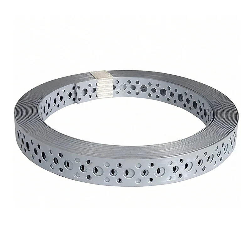
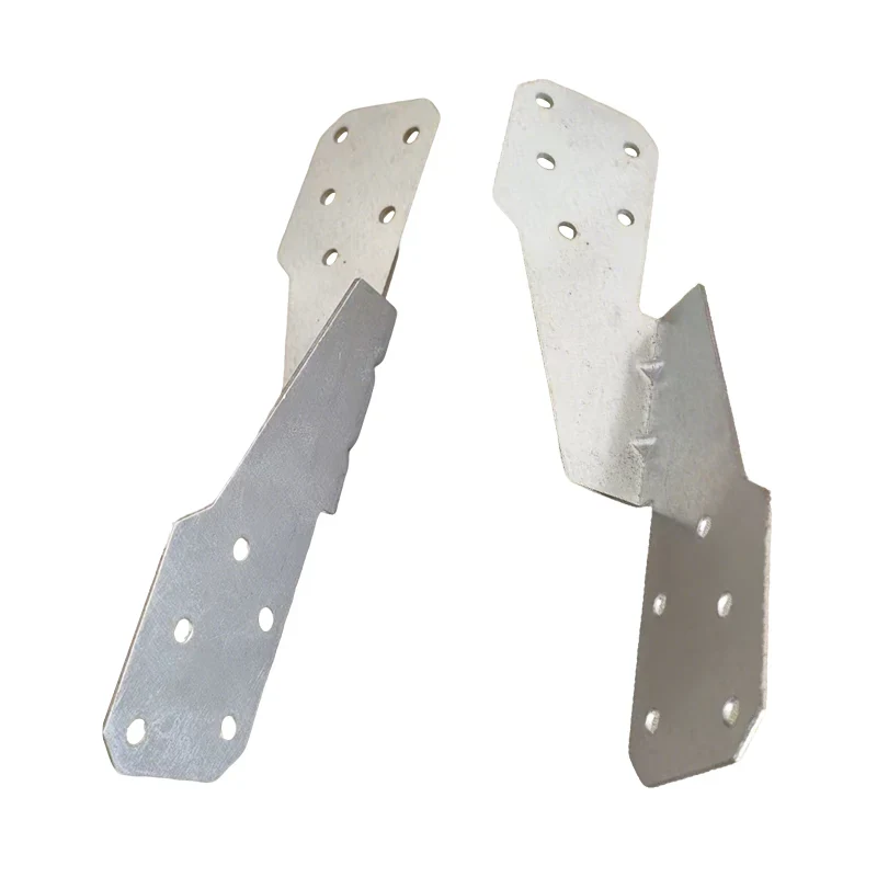
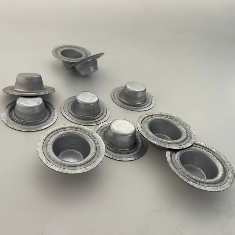
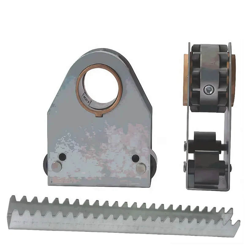
When an engineer specifies a Sheet Metal Fabrication Part for a new piece of industrial equipment, they often think of it as a single item—a bracket, an enclosure, a mounting plate. But behind that single part lies a complex, multi-stage manufacturing process that transforms a flat sheet of metal into a precision component. This process chain, known as full-cycle fabrication, encompasses everything from the initial design review to the final inspection and packaging. A part that looks simple on a drawing may require ten or more distinct operations, each with its own equipment, tooling, and quality control requirements. Understanding this full cycle is essential for engineers, procurement managers, and quality assurance teams who need to evaluate suppliers and ensure that their parts meet the required specifications.
A full-cycle Sheet Metal Fabrication Parts provider is not just a shop with a laser cutter and a press brake. It is a manufacturing partner that can manage the entire process, from material selection and design for manufacturability (DFM) analysis to cutting, forming, welding, surface treatment, and final assembly. Each stage of the process introduces variables that affect the final part's accuracy, strength, and appearance. A comprehensive understanding of these stages allows buyers to ask the right questions and to recognize a supplier who can deliver consistent quality. This article will guide you through the complete process chain for Sheet Metal Fabrication Parts, explaining each stage, its key parameters, and its impact on the final product.
Every Sheet Metal Fabrication Part begins as a 2D drawing or a 3D CAD model. The journey from that digital file to a finished, packaged part involves a sequence of operations that can be grouped into six major stages: design review, cutting, forming, welding, surface treatment, and quality control. Each stage is a link in a chain, and the strength of the chain is determined by its weakest link. A mistake in the design review can make the part impossible to manufacture; a poorly controlled cutting process can leave burrs that affect the fit; a sloppy weld can compromise structural integrity. A full-cycle fabricator manages all these stages under one roof, ensuring that each operation is optimized for the final part's requirements.
In our factory at Cangzhou Shengsen Metal Products Co., Ltd., we have organized our production floor around this full-cycle philosophy. The raw material warehouse feeds the cutting department, which in turn supplies the forming and bending department. The welded assemblies then move to the surface treatment area before entering the final inspection and packaging station. This linear flow is supported by a parallel flow of information—every part carries a traveler document that records its process history, material certification, and inspection results. This level of traceability is essential for industries such as automotive, aerospace, and medical equipment, where the consequences of a defective part can be severe.
The table below provides a high-level overview of the six stages and the key equipment involved:
| Stage | Primary Operations | Typical Equipment | Key Output |
| Design Review | DFM analysis, tolerance review | CAD/CAM software | Manufacturable design, process plan |
| Cutting | Laser cutting, plasma cutting, waterjet cutting | Fiber laser, CNC plasma, waterjet | Flat blanks with accurate contours |
| Forming | Bending, punching, deep drawing | Press brake, turret punch, stamping press | 3D formed shapes |
| Welding | MIG, TIG, spot welding | MIG welder, TIG welder, spot welder | Assembled structures |
| Surface Treatment | Powder coating, painting, plating | Powder coating line, paint booth, plating line | Protected, finished surface |
| Quality Control | Dimensional inspection, visual inspection | CMM, calipers, micrometers | Verified parts, inspection report |
Understanding this overview is the first step toward appreciating the complexity of full-cycle Sheet Metal Fabrication Parts. In the following sections, we will examine each stage in detail, focusing on the parameters that influence quality and the questions that buyers should ask their suppliers.
The design review is where the full-cycle process truly begins. Before any metal is cut, our engineering team receives the customer's 3D CAD model or 2D drawing and performs a Design for Manufacturability (DFM) analysis. This analysis is not a formality; it is a critical step that identifies potential manufacturing issues before they become costly problems. A DFM analysis for Sheet Metal Fabrication Parts typically examines several key factors. The first is the minimum bend radius. If the drawing specifies a bend radius that is smaller than the material thickness, the material may crack during bending. Our engineers will flag this and suggest a larger radius or a different material.
The second factor is the hole-to-bend distance. If a hole is located too close to a bend line, the hole will distort during bending. Our DFM analysis checks that all holes are at least 2.5 times the material thickness away from any bend. The third factor is the tolerance stack-up. Sheet metal fabrication involves multiple operations, and each operation has its own tolerance. The DFM analysis verifies that the cumulative tolerance of all operations is within the customer's specified overall tolerance. If it is not, we will discuss options such as tighter process controls or design modifications. The fourth factor is the material selection. Different materials have different formability, weldability, and corrosion resistance. Our engineers will review the specified material and suggest alternatives if a more cost-effective or better-performing option is available.
The output of the design review is a detailed process plan that specifies the sequence of operations, the equipment to be used, the tooling required, and the inspection criteria. This plan is shared with the customer for approval before production begins. The following table lists the common DFM issues we identify and our typical recommendations:
| DFM Issue | Potential Problem | Recommended Solution |
| Bend radius < material thickness | Cracking during bending | Increase bend radius or use a more ductile material |
| Hole too close to bend | Hole distortion | Move hole or increase distance to bend |
| Tolerance stack-up exceeds specification | Parts out of tolerance | Reduce number of operations or tighten process controls |
| Material not suitable for welding | Weak weld or cracking | Select a weldable material or change joining method |
| Sharp corners on cutouts | Stress concentration and tearing | Add corner radii to distribute stress |
At S-SEN, we consider the design review to be a value-added service. It is not just about catching errors; it is about optimizing the part for cost, quality, and performance. Our engineers have decades of combined experience in sheet metal fabrication, and they work closely with our customers to ensure that every part is designed for efficient production. By investing time in the design review, we prevent problems that would otherwise appear on the production floor, saving our customers time and money.
Cutting is the first physical operation in the fabrication of Sheet Metal Fabrication Parts. It is the process of separating a flat sheet of metal into the required blank shapes that will be formed and joined. The choice of cutting process depends on the material type, thickness, required accuracy, and production volume. The three most common cutting processes used in full-cycle fabrication are laser cutting, plasma cutting, and waterjet cutting. Each has its own strengths and limitations, and a full-cycle fabricator must have the expertise to select the right process for each job.
Laser Cutting: Laser cutting uses a focused, high-energy beam to melt and vaporize metal. It is the most precise cutting method, with a kerf width as narrow as 0.1 mm and positional accuracy of +/- 0.05 mm. Laser cutting is suitable for a wide range of materials, including mild steel, stainless steel, aluminum, copper, and brass. It produces a clean, burr-free edge that often requires no secondary finishing. The main limitation of laser cutting is the thickness of the material it can cut. A typical fiber laser can cut mild steel up to 25 mm thick, but the cutting speed decreases significantly as thickness increases. At our factory, we operate fiber laser cutting machines with power ratings from 2 kW to 12 kW, allowing us to cut a wide range of Sheet Metal Fabrication Parts with high efficiency.
Plasma Cutting: Plasma cutting uses a high-temperature plasma arc to melt the metal and a high-velocity gas stream to blow the molten material away. It is a faster and more economical method than laser cutting for thicker materials, particularly for mild steel and stainless steel. Plasma cutting can cut mild steel up to 50 mm thick or more. However, the cut edge is rougher than laser cutting, and the heat-affected zone is larger. Plasma cutting is often used for parts where the edge quality is not critical, such as structural brackets or supports. Our factory uses CNC plasma cutting tables for thicker parts, with a maximum cutting thickness of 60 mm.
Waterjet Cutting: Waterjet cutting uses a high-pressure stream of water, sometimes mixed with an abrasive material, to erode the metal. It is a cold cutting process, meaning there is no heat-affected zone. This makes it ideal for materials that are sensitive to heat, such as titanium and certain aluminum alloys. Waterjet cutting can cut almost any material, including glass, stone, and composites. It is also capable of cutting very thick materials, up to 200 mm. However, waterjet cutting is slower than laser or plasma cutting, and the abrasive material adds to the operating cost. We use waterjet cutting for specialized Sheet Metal Fabrication Parts where heat distortion must be avoided.
The table below compares the three cutting processes:
| Process | Max Thickness (mild steel) | Cut Quality | Heat-Affected Zone | Typical Applications |
| Fiber Laser | 25 mm | Excellent | Very small | Precision parts, enclosures, brackets |
| Plasma | 60 mm | Good | Moderate | Structural parts, thick brackets |
| Waterjet | 200 mm | Excellent | None | Heat-sensitive materials, thick plates |
At Cangzhou Shengsen Metal Products Co., Ltd., we maintain all three cutting technologies in-house. This allows us to select the optimal process for each Sheet Metal Fabrication Part, balancing cost, quality, and lead time. Our cutting department is equipped with advanced nesting software that optimizes material utilization, reducing waste and lowering costs for our customers.
Once the flat blanks have been cut, they must be formed into their three-dimensional shapes. This is accomplished through a variety of forming processes, the most common of which are bending, punching, and deep drawing. Bending is the most widely used forming process for Sheet Metal Fabrication Parts. It involves the use of a press brake, which clamps the sheet metal between a punch and a die and applies force to bend the material along a straight line. The accuracy of the bend angle and the bend radius are critical to the fit and function of the final part.
The press brake is a precision machine that requires skilled operators to set up and operate. The most important parameters in bending are the bend angle, the bend radius, the bend allowance, and the springback. Springback is the tendency of the metal to return partially to its original shape after the bending force is removed. It is a function of the material's yield strength and modulus of elasticity. To compensate for springback, the operator must over-bend the material slightly. Our factory uses CNC press brakes with automatic springback compensation, which calculates the required over-bend based on the material properties and the target angle. This ensures that the final bend angle is within +/- 0.5 degrees of the specification.
Punching is another common forming process. It involves the use of a turret punch press, which uses a variety of tools to punch holes, slots, and other features into the sheet metal. Punching is faster than laser cutting for high-volume production of holes, but it requires dedicated tooling for each hole size and shape. Deep drawing is a more specialized forming process used to create hollow, cup-like shapes from sheet metal. It is commonly used for parts such as enclosures, housings, and containers. Deep drawing requires a series of dies and presses, and it is typically used for high-volume production. Our factory has a range of deep drawing capabilities for specialized Sheet Metal Fabrication Parts.
The table below summarizes the key forming processes and their typical tolerances:
| Process | Typical Tolerance | Key Equipment | Typical Applications |
| Bending | +/- 0.5° (angle), +/- 0.1 mm (length) | CNC press brake | Brackets, enclosures, chassis |
| Punching | +/- 0.1 mm (hole position) | Turret punch press | Holes, slots, louvers |
| Deep Drawing | +/- 0.2 mm (diameter), +/- 0.1 mm (depth) | Hydraulic press, dies | Enclosures, housings, containers |
The forming department at Cangzhou Shengsen Metal Products Co., Ltd. is equipped with a range of CNC press brakes, turret punch presses, and hydraulic presses. Our operators are highly skilled and receive regular training on the latest forming techniques. We also use simulation software to predict springback and to optimize the bending sequence, ensuring that the first part is correct and that every subsequent part is identical.
After the individual components of a Sheet Metal Fabrication Part have been formed, they must be joined together. Welding is the most common joining method, and it is used to create strong, permanent bonds between metal parts. There are several welding processes used in sheet metal fabrication, each with its own characteristics and applications. The choice of welding process depends on the material type, the thickness of the parts, the required strength, and the appearance of the weld.
MIG Welding (Gas Metal Arc Welding): MIG welding is the most common welding process for sheet metal. It uses a continuous wire electrode that is fed through a welding gun. The wire melts and forms the weld bead, while an inert gas shield protects the weld from contamination. MIG welding is fast, versatile, and relatively easy to learn. It is suitable for a wide range of materials, including steel, stainless steel, and aluminum. However, MIG welding can produce a rougher weld bead than TIG welding, and it may produce spatter that requires cleanup.
TIG Welding (Gas Tungsten Arc Welding): TIG welding uses a non-consumable tungsten electrode to create an arc. A filler rod is added manually to the weld pool. TIG welding produces a very clean, precise weld with excellent appearance. It is often used for thin materials and for applications where the weld will be visible. TIG welding is slower than MIG welding and requires a higher level of skill. It is commonly used for stainless steel and aluminum Sheet Metal Fabrication Parts.
Spot Welding: Spot welding is a resistance welding process that uses pressure and electric current to join two overlapping metal sheets. It is fast and efficient, and it is widely used in the automotive industry for joining body panels. Spot welding does not require a filler material, and it produces a small, localized weld. However, spot welding is only suitable for overlapping joints, and it does not provide a continuous seal.
The table below compares the key welding processes:
| Process | Speed | Weld Appearance | Skill Required | Typical Applications |
| MIG Welding | Fast | Good | Moderate | General fabrication, structural parts |
| TIG Welding | Slow | Excellent | High | Thin materials, visible welds, stainless steel |
| Spot Welding | Very Fast | Good | Low | Automotive panels, overlapping joints |
At Cangzhou Shengsen Metal Products Co., Ltd., we have certified welders who are qualified to perform MIG, TIG, and spot welding on a variety of materials. Our welding department is equipped with modern welding machines and fume extraction systems. We also have a welding inspection program that includes visual inspection and, where required, non-destructive testing such as dye penetrant inspection. This ensures that every welded Sheet Metal Fabrication Part meets the required structural and quality standards.
The final stages of the full-cycle process are surface treatment and finishing. These operations are performed after the part has been cut, formed, and welded. The purpose of surface treatment is to protect the part from corrosion, to improve its appearance, and to provide a suitable surface for subsequent operations such as painting or assembly. There are several surface treatment options for Sheet Metal Fabrication Parts, and the choice depends on the material, the application, and the customer's requirements.
Powder Coating: Powder coating is the most common finishing process for sheet metal parts. It involves spraying a dry powder onto the part and then curing it in an oven. The powder melts and forms a hard, durable, and uniform coating. Powder coating is available in a wide range of colors and textures, and it provides excellent corrosion resistance. It is also an environmentally friendly process, as it does not use solvents. Our factory has a fully automated powder coating line with a capacity of 5,000 square meters per day.
Painting: Liquid painting is another common finishing process. It is often used for parts that require a specific color match or a smooth, glossy finish. Painting can be done by spray gun or by dipping. The paint is applied in multiple coats, with drying between coats. Liquid painting is more labor-intensive than powder coating, and it requires a controlled environment to prevent dust and other contaminants from affecting the finish.
Plating: Plating is an electrochemical process that deposits a thin layer of metal onto the surface of the part. Common plating materials include zinc, nickel, chrome, and tin. Plating is used to provide corrosion resistance, to improve solderability, or to enhance the appearance of the part. Zinc plating is the most common and is used for fasteners and brackets. Nickel and chrome plating are used for decorative applications.
Other Finishing Processes: Other finishing processes for Sheet Metal Fabrication Parts include anodizing (for aluminum parts), passivation (for stainless steel parts), and sandblasting (for surface preparation). Anodizing creates a hard, corrosion-resistant oxide layer on aluminum. Passivation removes free iron from the surface of stainless steel, improving its corrosion resistance. Sandblasting is used to clean and roughen the surface before painting or coating.
The table below summarizes the common surface treatment options:
| Process | Corrosion Resistance | Appearance | Typical Applications |
| Powder Coating | Excellent | Wide range of colors and textures | Enclosures, brackets, furniture |
| Liquid Painting | Good | Smooth, glossy finish | Automotive parts, appliances |
| Zinc Plating | Good | Silver or blue-white finish | Fasteners, brackets, electrical parts |
| Anodizing | Excellent | Clear, black, or colored | Aluminum parts, consumer electronics |
| Passivation | Excellent | Clean, natural metal finish | Stainless steel parts for food and medical |
The surface treatment department at Cangzhou Shengsen Metal Products Co., Ltd. is equipped with a range of processes, including powder coating, liquid painting, and zinc plating. We also work with trusted partners for specialized finishes such as anodizing and passivation. Our quality control team inspects the finish for adhesion, thickness, and appearance, ensuring that every Sheet Metal Fabrication Part meets the customer's specifications.
Quality control is not a single step at the end of the process; it is an integral part of every stage. However, the final inspection is the last opportunity to catch defects before the part is shipped to the customer. The inspection process for Sheet Metal Fabrication Parts includes dimensional inspection, visual inspection, and functional testing. The specific inspection criteria are defined in the process plan and are based on the customer's drawing and specifications.
Dimensional Inspection: Dimensional inspection verifies that the part's dimensions and geometry are within the specified tolerances. This is typically performed using a coordinate measuring machine (CMM), which can measure complex shapes with high accuracy. For simpler parts, calipers, micrometers, and height gauges may be used. The inspection report includes the measured values and the corresponding tolerance limits. Our factory uses a CMM with a measuring accuracy of +/- 0.002 mm to inspect critical dimensions on Sheet Metal Fabrication Parts.
Visual Inspection: Visual inspection checks the part for surface defects, such as scratches, dents, corrosion, and weld defects. It also verifies that the surface finish meets the specified requirements. Visual inspection is performed by trained inspectors who use a checklist to ensure consistency. For critical applications, the inspection may be performed under magnification or with the aid of a borescope to inspect internal features.
Functional Testing: Functional testing verifies that the part performs its intended function. This may include fit-up testing, where the part is assembled with mating components to ensure proper fit; load testing, where the part is subjected to a specified load to verify its strength; and leak testing, for parts that are required to be sealed. Functional testing is often performed on a sampling basis, but for critical parts, it may be performed on every unit.
The table below summarizes the quality control activities at each stage of the full-cycle process:
| Stage | Inspection Activity | Responsible Party | Acceptance Criteria |
| Design Review | DFM analysis | Engineering | All DFM issues resolved |
| Cutting | Dimensional check of blanks | QC Inspector | Within +/- 0.1 mm |
| Forming | Bend angle and dimension check | QC Inspector | Within +/- 0.5° and +/- 0.1 mm |
| Welding | Visual inspection, dye penetrant (if required) | Welding Inspector | No cracks, porosity, or undercut |
| Surface Treatment | Coating thickness, adhesion, appearance | QC Inspector | Within specified thickness, no defects |
| Final Inspection | Dimensional, visual, functional | QC Inspector | All criteria met, inspection report signed |
At Cangzhou Shengsen Metal Products Co., Ltd., our quality management system is certified to ISO 9001:2015. We maintain detailed records of all inspections, and we provide a certificate of conformance with every shipment. Our commitment to quality ensures that our customers receive Sheet Metal Fabrication Parts that meet their specifications and perform reliably in their applications.
Question 1: What is the typical lead time for full-cycle sheet metal fabrication parts?
Answer: The lead time for Sheet Metal Fabrication Parts depends on the complexity of the part, the quantity, and the surface treatment requirements. For standard parts with a simple finish, the lead time is typically 10-15 business days after design approval. For complex parts with multiple welds and a specialized finish, the lead time may be 20-30 business days. Our factory provides a detailed production schedule with every order, and we keep our customers informed of the progress throughout the manufacturing process.
Question 2: Can you provide a sample part before full production?
Answer: Yes, we can provide a sample part for approval before full production. The sample part is manufactured using the same processes and equipment that will be used for the production run, so it accurately represents the final product. The sample part is inspected and shipped with a detailed inspection report. Once the customer approves the sample, we proceed with full production. This sample approval process minimizes the risk of production errors and ensures that the final parts meet the customer's expectations.
Question 3: What materials do you work with for sheet metal fabrication?
Answer: We work with a wide range of materials for Sheet Metal Fabrication Parts, including mild steel, stainless steel (304, 316, 430), aluminum (5052, 6061), copper, brass, and galvanized steel. The choice of material depends on the application requirements, such as strength, corrosion resistance, and formability. Our engineering team can help you select the most suitable material for your specific application.
Question 4: How do you ensure the accuracy of your sheet metal fabrication parts?
Answer: We ensure the accuracy of our Sheet Metal Fabrication Parts through a combination of advanced equipment, skilled operators, and rigorous quality control. Our CNC machines are calibrated regularly, and our operators are trained to work within tight tolerances. We use a CMM for dimensional inspection and perform visual and functional testing on every batch. Our quality management system is certified to ISO 9001:2015, and we maintain detailed records of all inspections. If a part does not meet the specification, we will rework or replace it at no cost to the customer.
Question 5: What surface treatments are available for sheet metal fabrication parts?
Answer: We offer a range of surface treatments for Sheet Metal Fabrication Parts, including powder coating, liquid painting, zinc plating, anodizing, and passivation. The choice of surface treatment depends on the material, the application, and the desired appearance. Powder coating is the most common and provides excellent corrosion resistance and a wide range of colors. We also work with trusted partners for specialized finishes. Our team can help you select the best surface treatment for your part.
Full-cycle Sheet Metal Fabrication Parts are the result of a complex, multi-stage manufacturing process that transforms raw sheet metal into precision components. From the initial design review and DFM analysis to cutting, forming, welding, surface treatment, and final inspection, every stage contributes to the quality, durability, and performance of the final part. Understanding this full cycle is essential for engineers and procurement professionals who need to evaluate suppliers and ensure that their parts meet the required specifications. A full-cycle fabricator like Cangzhou Shengsen Metal Products Co., Ltd. manages all these stages under one roof, providing a single point of accountability and ensuring that every part is manufactured to the highest standards.
Our factory is equipped with advanced cutting, forming, welding, and finishing equipment, and our team of experienced engineers and skilled operators is dedicated to delivering high-quality Sheet Metal Fabrication Parts. We serve a wide range of industries, including automotive, aerospace, medical equipment, and industrial machinery. Whether you need a simple bracket or a complex enclosure, we have the expertise and the capacity to meet your requirements.
Contact Cangzhou Shengsen Metal Products Co., Ltd. today to discuss your Sheet Metal Fabrication Parts requirements and discover how our full-cycle capabilities can improve your supply chain.