Blind rivets, also known as pop rivets, are permanent mechanical fasteners used when only one side of a workpiece is accessible. They consist of a cylindrical body (shell) with a mandrel through the center. During installation, the mandrel is pulled into the shell, causing the blind side to deform and form a secondary head that clamps materials together.
The term "blind" refers to the installation condition, not the fastener itself. This type of rivet is widely applied in automotive assembly, sheet metal fabrication, aerospace structures, building cladding, and general manufacturing where access is limited to one side.
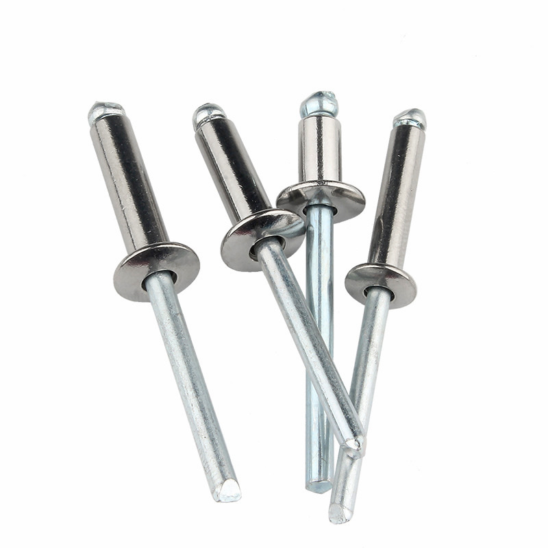
A blind rivet comprises four key sections:
| Component | Description |
| Rivet body (shell) | Hollow cylinder with a pre‑formed head (usually domed or countersunk) |
| Mandrel | Inner stem with a break point designed to separate at a specific tensile force |
| Setting head (on tool) | Tool component that grips the mandrel and provides pulling force |
| Blind‑side head | The deformed portion created during setting that clamps materials from the inaccessible side |
Principle of operation: The rivet tool grips the mandrel and pulls it outwards. As the mandrel is withdrawn, its enlarged tip forces the rivet body to expand radially on the blind side, forming a bulb‑shaped head. At a predetermined tension, the mandrel breaks at its neck point, leaving the set rivet in place.
Selection of rivet material shall be based on the base material being joined, environmental exposure, and mechanical load requirements.
Aluminum rivets (with steel or aluminum mandrel)
Most common type, suitable for general assembly
Lightweight, moderate shear and tensile strength
Used for sheet metal, HVAC ductwork, consumer products, automotive interiors
Steel rivets (zinc‑plated or plain)
Higher strength than aluminum
Suitable for structural applications and heavy gauge materials
Used in steel framing, machinery guards, industrial equipment
Stainless steel rivets
Corrosion‑resistant, suitable for outdoor and marine environments
Higher strength and hardness, requires more powerful installation tools
Used in marine hardware, architectural cladding, chemical processing equipment
Copper and brass rivets
Good electrical conductivity and corrosion resistance
Used in electrical applications, decorative hardware, leather goods
Monel (nickel‑copper alloy) rivets
Excellent corrosion resistance in seawater and chemical environments
High strength and temperature resistance
Used in marine engineering, chemical plants, offshore structures
Diameter: The rivet diameter refers to the outer diameter of the body. Common sizes include 2.4 mm (3/32"), 3.2 mm (1/8"), 4.0 mm (5/32"), 4.8 mm (3/16"), 5.6 mm, 6.4 mm (1/4"). Diameter selection is based on the load‑bearing requirement: larger diameters offer higher shear and tensile strength.
Grip range: This is the total thickness of materials being joined. Each rivet size covers a specific grip range, typically provided by the manufacturer.
| Diameter | Typical Grip Range | Application Thickness |
| 2.4 mm | 1.0~3.0 mm | Thin sheet and electronics |
| 3.2 mm | 1.5~4.5 mm | Light sheet metal |
| 4.0 mm | 2.0~5.0 mm | Medium sheet assembly |
| 4.8 mm | 2.5~6.5 mm | General structural connections |
| 6.4 mm | 3.0~8.0 mm | Heavy‑duty applications |
Critical rule: Grip range must cover the actual material thickness. If rivet is too short, it cannot form a proper blind head, resulting in joint failure. If too long, the mandrel may not break cleanly, leaving excess body protruding.
Proper hole preparation is essential for reliable rivet performance.
Hole diameter: The hole shall be 0.1~0.2 mm larger than the rivet body diameter. Oversized holes reduce shear strength and allow joint movement. Undersized holes can damage the rivet body during insertion and may cause setting difficulties.
| Rivet Diameter | Recommended Hole Size |
| 2.4 mm | Φ2.5~2.6 mm |
| 3.2 mm | Φ3.3~3.4 mm |
| 4.0 mm | Φ4.1~4.2 mm |
| 4.8 mm | Φ4.9~5.0 mm |
| 6.4 mm | Φ6.5~6.6 mm |
Edge distance: The hole center shall be at least 2× rivet diameter from the edge of the material. Insufficient edge distance leads to material tear‑out when the rivet is loaded.
Material alignment: All layers must be properly aligned before drilling or punching. Burrs shall be removed from both sides of the hole to ensure the rivet body seats flush against the workpiece.
Step 1: Select the correct rivet Confirm diameter, grip range, and material are appropriate for the application.
Step 2: Prepare the workpieces Drill or punch holes through all layers. Remove burrs and clean surfaces. Clamp materials together to prevent separation during riveting.
Step 3: Insert the rivet Place the rivet through the hole from the accessible side. The pre‑formed head should sit flat against the top surface. Ensure the rivet body extends completely through all layers.
Step 4: Position the rivet tool Fit the appropriate nosepiece onto the rivet tool. Place the nosepiece over the rivet mandrel, ensuring full engagement.
Step 5: Operate the tool Squeeze or activate the tool to pull the mandrel. Continue until the mandrel breaks at the designated neck point. A properly set rivet will show the blind head fully formed and the broken mandrel flush with or slightly below the factory head.
Step 6: Inspect the installation Check that:
The factory head is seated flush against the material
No gap exists between materials
The blind head is fully formed (visible from accessible side by the pull‑up of material if applicable)
Mandrel break is clean and at the correct depth
| Defect | Observable Sign | Probable Cause |
| Incomplete blind head | Blind side shows little or no deformation | Rivet too long for material thickness; insufficient pull force |
| Broken mandrel before seating | Mandrel breaks without clamping materials | Tool nosepiece too small; rivet too short; material pack‑out excessive |
| Damaged factory head | Cracks or deformation on accessible side | Excessive force; misaligned tool; brittle material |
| Loose joint | Materials can be separated or moved after setting | Incorrect grip range; hole oversized; insufficient setting cycle |
| Mandrel stuck in tool | Mandrel does not eject after break | Nosepiece worn; foreign matter in tool; incorrect nosepiece size |
| Oval or deformed hole | Hole shape distorted after setting | Hole oversized; materials misaligned; excessive lateral load |
Manual rivet pliers Suitable for occasional use and light applications. Models available for rivet diameters up to 4.8 mm. Leverage design varies: single‑handle for small rivets, compound‑action for larger sizes.
Pneumatic rivet guns Air‑powered tools suitable for high‑volume production. Offer consistent pulling force and faster cycle times. Required for large diameter rivets and stainless steel types. Air supply typically 5~7 bar.
Battery‑powered rivet tools Portable and suitable for field applications. Offer sufficient force for most general‑purpose rivets up to 4.8 mm. Battery technology provides cordless convenience but with limited cycle capacity per charge.
Hydraulic and servo riveters Used for heavy industrial applications, including high‑strength structural rivets. Provide precise pull force monitoring and data tracking for quality assurance.
Nosepiece selection: Each rivet diameter requires a corresponding nosepiece. Swapping nosepieces is necessary when changing rivet sizes. Some tools offer quick‑change systems for production efficiency.
Blind rivet joints are typically designed for shear loads (forces parallel to the joint plane), not primary tensile loads (forces pulling materials apart).
Shear strength is the maximum force the rivet can withstand perpendicular to its axis. This is the primary design parameter for most lap joints.
Tensile strength is the maximum pulling force the rivet can withstand along its axis. Generally lower than shear strength for most blind rivet types.
Fatigue performance: Blind rivets have lower fatigue resistance compared to solid rivets due to the hollow body and stress concentration at the mandrel hole. For cyclic loading applications, structural rivets or high‑strength types (such as monel or steel) shall be considered.
Joint design recommendation: Use multiple rivets in a staggered pattern rather than a single rivet in a heavily loaded joint. Minimum spacing between rivets is 3× rivet diameter to avoid material weakening.
Dissimilar materials in contact create galvanic corrosion risk. Select rivet material compatible with the base material.
| Base Material | Recommended Rivet Material |
| Aluminum sheet | Aluminum (with steel mandrel acceptable) |
| Steel sheet (painted/unpainted) | Steel (zinc‑plated) or stainless steel |
| Stainless steel sheet | Stainless steel |
| Copper alloys | Brass or copper |
| Marine environments | Monel or stainless steel 316 |
Rule: Rivets shall be cathodic (more noble) relative to the base material to avoid accelerated corrosion of the base material. If uncertain, insulate with sealant or gaskets.
Sealed rivets: Featuring a closed‑end body that prevents water or gas leakage through the center. Used in waterproof applications, pressure vessels, and weather‑exposed structures.
Multi‑grip rivets: Designed to cover a wider grip range, reducing inventory requirements. Suitable for applications with varying material thicknesses.
Self‑piercing rivets (SPR): Installed without pre‑drilled holes. The rivet pierces through the top layer and flares into the bottom layer. Used in automotive body assembly, particularly for aluminum and mixed‑material joints.
Breakstem rivets: The mandrel head remains captive within the rivet body after setting, preventing the mandrel from dropping out. Required in applications where loose mandrels could cause contamination (food processing, electronics).
Grooved rivets: Feature a grooved body for improved pull‑up performance in soft materials such as plastic, wood, or composites.
Rivets shall be stored in dry, clean conditions with protection from moisture and contaminants. Aluminum and steel rivets can oxidize in humid environments, affecting setting performance and corrosion resistance.
Store in original packaging until use
Keep storage area humidity below 60%
Avoid exposure to oils, solvents, and industrial dust
Rotate inventory on a first‑in‑first‑out basis
Rivets stored for extended periods (over 24 months) shall be inspected for corrosion or degradation prior to use
Visual inspection (installation check):
Factory head is flush and concentric
Mandrel break is clean and visible below head
No cracks or distortion on either side
Tensile pull test: Periodically pull‑test sample rivets using a tensile tester to confirm shear and tensile values meet specifications. Minimum sample: 5 rivets per batch.
Grip test: Verify that the remaining mandrel length inside the set rivet is within acceptable limits (typically 0.5~1.5 mm below head surface).
Destructive inspection: Cross‑section selected rivets to inspect blind‑head formation and confirm adequate material deformation. This is especially important during process validation and tool change validation.
| Problem | Immediate Check | Solution |
| Rivet spins in hole | Hole diameter too large | Replace with larger diameter rivet; correct hole size |
| Cannot insert rivet | Hole diameter too small | Ream hole to correct size |
| Tool cannot pull | Incorrect nosepiece or worn tool jaw | Replace nosepiece; service tool |
| Mandrel breaks too early | Grip range too short | Use longer grip rivet |
| Mandrel won't break | Insufficient pull force | Use more powerful tool; check air pressure |
| Blind head not formed | Rivet too long or tool malfunction | Verify grip range; check tool operation |
| Materials separate after setting | Insufficient clamping force | Shorten grip range; increase hole fit accuracy |
This guide provides fundamental reference for selection and installation of blind rivets. For critical applications, consult manufacturer technical specifications and perform qualification testing on representative assemblies prior to production.